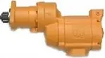
Ingersoll Rand literature · Installation & maintenance manual
Ingersoll Rand SS875 Series Turbine Starter Installation and Maintenance Manual (P6800)
The Ingersoll-Rand installation and maintenance manual for the Series SS875 turbine starter, a starter designed for gas operation, built with a vane motor, a sprag clutch and a splined output shaft, and offered in 0.74:1 and 1.35:1 gear ratios. It covers lubrication, installation and re-orientation, engine mounting, complete disassembly and assembly with torque values, a bench test, a troubleshooting guide and the illustrated parts list. It is written for installers and service technicians maintaining SS875G074L, SS875G135L and SS875G135R starters.
Document at a Glance
- Publisher
- Ingersoll Rand
- Document type
- Installation & maintenance manual
- Form / number
- Form P6800, No. 03534864, Edition 1
- Language
- English
- Pages
- 12
- File
- PDF, 1.2 MB
What's in This Document
| Section | Pages | What it covers |
|---|---|---|
| Introduction and warning | 1 | Pressure-rating caution, gas-operation warnings and the requirement to test any rebuilt starter. |
| Mounting dimensions and piping diagram | 2 | Dimension drawing (Dwg. TPA1152) and recommended piping layout; drawing text is not machine-readable. |
| Lubrication | 3 | Lubricator choice, oil specification and flow setting for cranking cycles over 10 seconds. |
| Installation: general information and orientation | 3 | Hose sizing, sealing and leak checks, plus how to re-clock the drive housing, motor housing and inlet. |
| Mounting the starter | 4 | Fifteen steps from lubricator and hose routing through splined-shaft fitting, mounting torque and clutch oil connections. |
| Disassembly of the starter | 4-5 | Teardown of the drive housing, clutch assembly, motor and gear case, with ratio- and rotation-specific notes. |
| Assembly of the starter | 7-8 | Rebuild sequence for the drive housing and motor, including clearances, grease quantity and fastener torques. |
| Test and inspection procedure | 8 | Clutch, freeness, vane action and seal checks for a reassembled starter. |
| Troubleshooting guide | 9 | Causes and fixes for power loss, air or gas leakage and a motor that runs without turning the shaft. |
| Series SS875 Turbine Starter parts drawing (Dwg. TPA1150) | 10 | Exploded drawing keyed to the parts list. |
| Parts list (part number for ordering) | 11 | Ordering numbers with ratio and rotation variants and recommended spares flagged. |
Key Specifications and Data
| Item | Value | Page |
|---|---|---|
| Gear ratios | 0.74:1 and 1.35:1 | 11 |
| Lubricator for cranking cycles over 10 seconds | Ingersoll-Rand NL-24-8, set to 200 to 500 cc/min (or engine high-pressure oil above air inlet pressure) | 3 |
| Lubricating oil | MIL-L-23699B or SAE 10W non-detergent oil | 3 |
| Supply line size | 1-1/2 in hose or pipe up to 15 ft; 2 in over 15 ft | 3 |
| Inlet and exhaust connections | 1-1/2 in SAE J518C flanged inlet; 2-1/2 in SAE J518C flanged exhaust | 11 |
| Drive housing cap screw torque | 28 ft-lb (38 N m) | 3 |
| Motor housing cover cap screw torque | 60 ft-lb (81.4 N m) | 3 |
| Starter mounting nut torque | 30 ft-lb (41 N m) | 4 |
| Rotor pinion retaining screw torque | 90 ft-lb (122 N m) | 8 |
| Clutch oil supply | .050 in orifice fitting fed from engine oil at about 50 psi, return to engine sump | 4 |
| Drive gear grease | 8 oz (240 mL) of Ingersoll-Rand No. 28 Grease | 7 |
| Rear end plate to rotor clearance | .001 in (.02 mm) to .003 in (.07 mm) | 7 |
| Vane replacement limit | Width of 15/16 in (24 mm) or less at either end | 5 |
| Motor seal test | 30 psig (207 kPa), exhaust plugged, immersed 30 seconds | 8 |
| Drive housing positions | 16 radial positions relative to the gear case; exhaust and inlet each 4 positions | 3 |
| Pressurized oil inlet | 3/8 in NPT on the side of the motor housing cover | 4 |
Ratio-specific parts
| Part | 0.74:1 ratio | 1.35:1 ratio |
|---|---|---|
| Rotor pinion | SS875-17 | M800A-17 |
| Drive gear | SS875-9 | M800A-9 |
| Rear clutch bearing | SS875-399 | CGH20A-518 |
| Front drive shaft bearing | SS875-363 | R4800-97 |
| Front clutch shaft bearing | SS875-278 | G7-24 |
| Splined shaft, 24 teeth | SS875-13 | SS875-13A |
Fastener torques
| Fastener | ft-lb | N m |
|---|---|---|
| Drive housing cap screws | 28 | 38 |
| Motor housing cover cap screws | 60 | 81.4 |
| Starter mounting nuts | 30 | 41 |
| Rotor pinion retaining screw | 90 | 122 |
Models Covered
Model codes as printed in the document. Linked codes go to the matching Ingersoll Rand starter in our catalog.
SS875G074L SS875G135L SS875G135R
Service Kits and Part Numbers
| Part number | Description | Page |
|---|---|---|
| SS800-140 | Motor housing (2-1/2 in SAE J518C flanged exhaust) | 11 |
| SS800-A202 | Motor housing cover assembly (1-1/2 in SAE J518C flanged inlet) | 11 |
| SS800-K3 | Cylinder kit | 11 |
| SS800-67 | Cylinder O-ring | 11 |
| SS800R-12 | Rear end plate for model SS875G135R | 11 |
| SS800-24 | Rear rotor bearing | 11 |
| HRA20A-990 | Rear rotor bearing O-ring | 11 |
| SS825-53 | Rotor | 11 |
| M800-42-5 | Vane packet (set of 5 vanes) | 11 |
| SS800G-11 | Front end plate | 11 |
| SS800-22 | Front rotor bearing | 11 |
| SS875-17 | Rotor pinion, 0.74:1 ratio | 11 |
| M800A-17 | Rotor pinion, 1.35:1 ratio | 11 |
| SS800-37 | Gear case | 11 |
| SS875-9 | Drive gear, 0.74:1 ratio | 11 |
| M800A-9 | Drive gear, 1.35:1 ratio | 11 |
| SS800-152 | Bulkhead O-ring | 11 |
| SS875-150 | Bulkhead | 11 |
| SS875-272 | Bulkhead seal | 11 |
| SS800-244 | Drive housing O-ring | 11 |
| SS875-8 | Drive gear shaft | 11 |
| SS875-14 | Clutch shaft | 11 |
| SS875-587 | Clutch | 11 |
| SS875-13 | Splined shaft, 24 teeth (0.74:1 ratio) | 11 |
| SS875-13A | Splined shaft, 24 teeth (1.35:1 ratio) | 11 |
| SS875-13B | Splined shaft, 14 teeth (12/24 diametral pitch) | 11 |
| SS875-271 | Drive housing seal | 11 |
| SS875-300 | Drive housing | 11 |
| NL-24-8 | Lubricator | 11 |
Confirm part numbers against the serial and model plate of your starter. For any part not listed in our catalog, send us the number.
Mounting the SS875 starter (Overview)
- Plan the hookup from the piping diagram and confirm the air or gas supply is rated for the starter's maximum operating pressure.
- Join the NL-24-8 lubricator and pressure regulator with a 1-1/2 in NPT close nipple, or use engine high-pressure oil above starter inlet pressure.
- Measure and run 1-1/2 in hose from the lubricator or regulator to the starter location.
- Grease both ends of the splined shaft and insert it (single-groove end into the starter when only one O-ring groove is present).
- Lift the starter into place and tighten the mounting nuts to 30 ft-lb (41 N m), then install the exhaust system.
- Connect the clutch oil supply through the .050 in orifice fitting (port 30 degrees above center) and the return line (30 degrees below center) to the sump.
- Pressurize the system and soap-test every connection for leaks.
An outline only. Follow the full procedure, torque values and safety warnings in the document (from page 4).
Test and inspection after assembly (Overview)
- Clutch check: insert the splined shaft into the clutch shaft and turn it in the direction the manual gives for the starter's rotation; it should turn freely.
- Freeness check: turn the splined shaft the other way by hand to confirm the motor and gearing turn.
- Supply 90 psig to the motor inlet through a 3/8 in line; the starter should run smoothly.
- Plug the exhaust, apply 30 psig to the inlet and immerse the starter in non-flammable solvent for 30 seconds; no bubbles should appear.
An outline only. Follow the full procedure, torque values and safety warnings in the document (from page 8).
Frequently Asked Questions
What gear ratios does the Ingersoll Rand SS875 turbine starter come in?
The parts list covers 0.74:1 and 1.35:1 ratios, with different rotor pinions, drive gears, bearings and splined shafts for each.
How should an SS875 starter be lubricated?
For cranking cycles longer than 10 seconds the manual recommends the NL-24-8 lubricator set to 200-500 cc/min, or an engine high-pressure oil line whose pressure exceeds the air inlet pressure, using MIL-L-23699B or SAE 10W non-detergent oil.
What are the SS875 mounting and housing bolt torques?
Mounting nuts are tightened to 30 ft-lb (41 N m), drive housing cap screws to 28 ft-lb (38 N m) and motor housing cover cap screws to 60 ft-lb (81.4 N m).
When should SS875 vanes be replaced?
Replace the full vane set if any vane is cracked, spalled or worn to 15/16 in (24 mm) wide or less at either end.
Does the SS875 clutch need an oil supply?
Yes. The manual has you connect engine oil at about 50 psi through a .050 in orifice fitting in the drive housing, with a return line to the engine sump.
Need the parts or the starter in this document? Send the model number from your starter's plate and we will confirm the right Ingersoll Rand part or replacement.
Source: Ingersoll Rand, Form P6800, No. 03534864, Edition 1. Summary and tables prepared by AirStartersDirect.com, an authorized Ingersoll Rand air starter distributor; the PDF is the authoritative version. Page numbers refer to the PDF file. Reviewed October 2026.
Turbine Air Starter Category Links

Updated turbine starter from Ingersoll Rand for engines from 16-95 liters.

Powerful 70 hp turbine motor offers best-in-class performance in the harshest conditions!

NEWEST MODEL! Unlocks unprecedented productivity for engines ranging from 15 up to 150 liters!

Industrial duty air starter for engines 5 to 60 liters (Diesel). Commonly used in marine, trucking, transit, and oil & gas applications.

Industrial duty air starter for engines 16 to 80 liters (Diesel). Commonly used in mining and marine applications.

For engine displacement of: Diesel 16 to 320 liters Industry applications for the ST700 and ST900 Series starters - oil and gas, marine, power-gen, and transportation.

Industrial duty air starter for engines 5 to 60 liters (Diesel). Commonly used in marine, trucking, transit, and oil & gas applications.
Vane Air Starter, Gas Turbine Starter, and Engine Barring Motor Category Links

NEW! One Size fits engines up to 10+ liters.

For Diesel engines 8 - 32 liters.

Sealed for Gas applications.

For Diesel engines 3 to 20 liters.

For Diesel engines 16 - 320 liters.

For service work on diesel engines.
Questions? Need Help Finding The Right air Starter? Use Our Fast Response Form Below
