Ingersoll Rand literature · Installation & maintenance manual
Ingersoll Rand ST600 Series Turbine Air Starter Installation and Maintenance Manual (04662995)
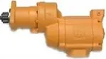
This is the Ingersoll Rand installation and maintenance manual for the ST600 Series pre-engaged turbine air starter with an SAE 03 flange. It is written for installers and service technicians. It explains how the model code is built, gives pinion data, shows stationary and vehicular piping layouts and mounting dimensions, and walks through orientation, mounting, lubrication, disassembly, reassembly and troubleshooting, with an illustrated parts list.
Document at a Glance
- Publisher
- Ingersoll Rand
- Document type
- Installation & maintenance manual
- Form / number
- No. 04662995, Edition 4, December 2006
- Language
- English
- Pages
- 16
- File
- PDF, 1.1 MB
What's in This Document
| Section | Pages | What it covers |
|---|---|---|
| General Product Safety Information | 2 | Safety warnings and notices covering air pressure limits, hoses, compressed-air-only operation, protective equipment and use of genuine parts. |
| Placing Starter in Service (How to Order a Starter) | 3 | Breaks down the ST600 model code and lists the five available drive pinions with tooth count, pitch and diameters. |
| Installation | 4 | Covers supply line sizing, inlet strainers, sealing connections, re-orienting the drive housing and the step-by-step mounting of the starter and its controls. |
| Piping Diagram | 5 | Typical stationary and vehicular pre-engaged installations with the Ingersoll Rand part numbers of each component. |
| ST600 Pre-Engaged Mounting Dimensions | 6 | Dimensional drawing in inches and millimetres with the inlet flange kit, control ports, orientation options and starter weight. |
| Section View and Exploded Diagram | 7-8 | Cross-section and exploded drawings that key the item numbers used in the parts list. |
| Parts List | 9 | Item-by-item part numbers, including left- and right-hand motor and drive assemblies and the pinion for each model. |
| Maintenance: Lubrication and Disassembly | 10 | Which Ingersoll Rand greases go where, general overhaul rules and the order for taking the starter apart. |
| Assembly of the Starter | 11 | Reassembly sequence with transmission fluid fill quantities and fastener torques. |
| Troubleshooting Guide | 11 | Table of symptoms such as no rotation or loss of power, with likely causes and fixes. |
| Parts and Maintenance | 12 | Notice on genuine replacement parts, authorized repair and recycling the starter at end of life. |
Key Specifications and Data
| Item | Value | Page |
|---|---|---|
| Mounting flange | SAE 03 | 3 |
| Engagement type | Pre-engaged (P) | 3 |
| Starter weight | 39 lb | 6 |
| Maximum operating pressure | Pressure rating stamped on the starter nameplate | 2 |
| Supply line size | 1-1/2 in hose or pipe up to 15 ft; 2 in if longer than 15 ft | 4 |
| Inlet strainer | 300 mesh (50 micron filtration) | 4 |
| Relief valve setting (stationary piping) | 15 psi above regulator setting | 5 |
| Mounting bolt torque | 100 ft-lb (136 Nm) | 4 |
| Exhaust cap torque | 50 ft-lb | 11 |
| Drive housing cap screw torque | 20-25 ft-lb | 11 |
| Drive pinion retaining screw torque | 180-220 ft-lb | 11 |
| Gear case fluid fill | 275 ml automatic transmission fluid through the front deflector | 11 |
| Exhaust cover fluid fill | 20 ml automatic transmission fluid | 11 |
| Greases | Ingersoll Rand No. 130 (drive shaft bore, drive housing, piston, return spring); No. 11 (pinion end of drive shaft) | 10 |
| Drive housing positions | 8 radial positions (45 degree steps) relative to the air inlet | 4 |
| Pinion retaining screw thread | Left-hand on R31/R51/R83/R91/R942 models; right-hand on L-suffix models | 10 |
ST600 drive pinion data
| Pinion part number | Teeth | Blank | DP/Module | Pitch diameter (in) | Pitch diameter (mm) | Pressure angle | Rotation | OD (in) | OD (mm) |
|---|---|---|---|---|---|---|---|---|---|
| ST600-13-31 | 12 | 12 | 6/8 | 2.000 | 50.80 | 20.0 | R/L | 2.250 | 57.15 |
| ST600-13-51 | 15 | 15 | 6/8 | 2.500 | 63.50 | 20.0 | R/L | 2.750 | 69.85 |
| ST600-13-83 | 12 | 12 | 3.5 Module | 1.515 | 38.50 | 20.0 | R/L | 1.882 | 47.80 |
| ST600-13-91 | 14 | 16 | 3.5 Module | 1.929 | 49.00 | 20.0 | R/L | 2.441 | 62.00 |
| ST600-13-942 | 14 | 15 | 3.5 Module | 1.929 | 49.00 | 15.0 | R/L | 2.301 | 58.45 |
ST600 model code positions (example ST6 50 B P 03 R 31 045)
| Position | Meaning | Options printed |
|---|---|---|
| ST6 | Starter series | ST600 |
| 50 / 99 | Arc | 50 = half, 99 = full |
| B | Gear ratio | B |
| P | Engagement | P = pre-engaged |
| 03 | Flange | 03 = SAE 03 |
| R / L | Pinion rotation | R = right, L = left |
| 31 | Pinion code | 31, 51, 83, 91, 942 |
| 045 | Orientation | 045, 090, 135, 180, 225, 270, 315 |
Models Covered
Model codes as printed in the document. Linked codes go to the matching Ingersoll Rand starter in our catalog.
ST650BP03L942 ST650BP03R942 ST699BP03L942 ST699BP03R942 ST650BP03L91 ST650BP03R91 ST699BP03L91 ST699BP03R91 ST650BP03L83 ST650BP03R83 ST650BP03L51 ST650BP03R51 ST699BP03L51 ST699BP03R51 ST650BP03L31 ST650BP03R31 ST699BP03L31 ST699BP03R31
Service Kits and Part Numbers
| Part number | Description | Page |
|---|---|---|
| ST650L-A53B | Motor assembly, LH rotation models | 9 |
| ST650R-A53B | Motor assembly, RH rotation models | 9 |
| ST600C-APGR | Gear package assembly | 9 |
| ST600L-APDR | Drive package assembly, LH rotation models | 9 |
| ST600R-APDR | Drive package assembly, RH rotation models | 9 |
| ST600-K300 | Drive housing assembly | 9 |
| ST600-A40 | Motor housing assembly | 9 |
| ST700-K166 | Inlet flange kit (includes mounting hardware) | 9 |
| ST600-703 | Piston | 9 |
| ST600-700 | Spring | 9 |
| ST600-175 | Pinion collar | 9 |
| ST600-13-31 | Drive pinion for models ending in L31 or R31 | 9 |
| ST600-13-51 | Drive pinion for models ending in L51 or R51 | 9 |
| ST600-13-83 | Drive pinion for ST650BP03L83 and ST650BP03R83 | 9 |
| ST600-13-91 | Drive pinion for models ending in L91 or R91 | 9 |
| ST600-13-942 | Drive pinion for models ending in L942 or R942 | 9 |
| ST600L-394 | Pinion retaining screw, LH rotation models | 9 |
| ST600R-394 | Pinion retaining screw, RH rotation models | 9 |
| ST900-267-24 | 300 mesh inlet strainer for 1-1/2 in lines | 4 |
| ST900-267-32 | 300 mesh inlet strainer for 2 in lines | 4 |
| ST900-267-64 | 300 mesh inlet strainer for 4 in lines | 4 |
| ST900-266-24 | Replacement strainer element, 1-1/2 in | 4 |
| ST900-266-32 | Replacement strainer element, 2 in | 4 |
| ST900-266-64 | Replacement strainer element, 4 in | 4 |
| SRV150 | Starter relay valve | 5 |
| SMB-618 | Starter control valve (brass, air) | 5 |
| 150BMP-1064L | Air pressure gauge | 5 |
| 150BMP-1051B | Solenoid valve, 12 volt (vehicular) | 5 |
| 150BMP-2450 | Solenoid valve, 120 volt (stationary) | 5 |
| SMB-441 | Pipe thread sealant | 5 |
Confirm part numbers against the serial and model plate of your starter. For any part not listed in our catalog, send us the number.
Mounting the air starter (Overview)
- Check that the receiver tank meets SAE J10B and is rated at least to the starter operating pressure; bleed and drain an in-service tank first.
- Fit the SRV150 relay valve to the tank with a 1-1/2 in short nipple, using the inlet side marked IN.
- Mount the starter control valve and pressure gauge on the panel and connect them to the relay valve with 1/4 in hose and a tee.
- Run 1-1/2 in hose from the relay valve outlet to the starter location, attaching it before mounting if access is tight.
- Grease the ring gear teeth if possible, mount the starter on the flywheel housing and torque the bolts to 100 ft-lb (136 Nm).
- Pressurize the system and soap-test every connection for leaks.
An outline only. Follow the full procedure, torque values and safety warnings in the document (from page 4).
Reassembling the starter (Overview)
- Insert the gear package into the motor housing and align the planet gears with the ring gear.
- Fit the wave spring and front deflector, then add 275 ml of automatic transmission fluid through the deflector hole.
- Lubricate the motor O-rings and cylinder and install the motor assembly from the rear, geared end forward.
- Install the exhaust cap and torque to 50 ft-lb, then add 20 ml of transmission fluid through the exhaust cover screw hole.
- Engage the drive package splines with the gear package, fit the spring and seat, and torque the drive housing screws to 20-25 ft-lb.
- Fit the pinion and collar and torque the retaining screw to 180-220 ft-lb, noting the thread hand for the model.
An outline only. Follow the full procedure, torque values and safety warnings in the document (from page 11).
Frequently Asked Questions
What size air supply line does an ST600 starter need?
The manual calls for 1-1/2 inch hose or pipe on runs up to 15 feet and 2 inch hose or pipe on longer runs, with as few tees and elbows as possible.
How much transmission fluid goes in an ST600 starter?
During assembly 275 ml of automatic transmission fluid is added through the front deflector, and another 20 ml through the exhaust cover screw hole after the cover is fitted.
What is the torque for the ST600 pinion retaining screw?
180-220 ft-lb. Models ending in R31, R51, R83, R91 or R942 use a left-hand thread; L-suffix models use a right-hand thread.
Which pinion fits my ST600 model?
The last digits of the model code match the pinion: 31 uses ST600-13-31, 51 uses ST600-13-51, 83 uses ST600-13-83, 91 uses ST600-13-91 and 942 uses ST600-13-942.
How much does an ST600 starter weigh?
The mounting dimension drawing gives the starter weight as 39 lb.
Need the parts or the starter in this document? Send the model number from your starter's plate and we will confirm the right Ingersoll Rand part or replacement.
Source: Ingersoll Rand, No. 04662995, Edition 4, December 2006. Summary and tables prepared by AirStartersDirect.com, an authorized Ingersoll Rand air starter distributor; the PDF is the authoritative version. Page numbers refer to the PDF file. Reviewed October 2026.
Turbine Air Starter Category Links

Updated turbine starter from Ingersoll Rand for engines from 16-95 liters.

Powerful 70 hp turbine motor offers best-in-class performance in the harshest conditions!

NEWEST MODEL! Unlocks unprecedented productivity for engines ranging from 15 up to 150 liters!

Industrial duty air starter for engines 5 to 60 liters (Diesel). Commonly used in marine, trucking, transit, and oil & gas applications.

Industrial duty air starter for engines 16 to 80 liters (Diesel). Commonly used in mining and marine applications.

For engine displacement of: Diesel 16 to 320 liters Industry applications for the ST700 and ST900 Series starters - oil and gas, marine, power-gen, and transportation.

Industrial duty air starter for engines 5 to 60 liters (Diesel). Commonly used in marine, trucking, transit, and oil & gas applications.
Vane Air Starter, Gas Turbine Starter, and Engine Barring Motor Category Links

NEW! One Size fits engines up to 10+ liters.

For Diesel engines 8 - 32 liters.

Sealed for Gas applications.

For Diesel engines 3 to 20 liters.

For Diesel engines 16 - 320 liters.

For service work on diesel engines.
Questions? Need Help Finding The Right air Starter? Use Our Fast Response Form Below
