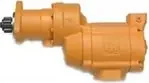
Ingersoll Rand literature · Installation & maintenance manual
Ingersoll Rand ST400 Turbine Powered Air Starter Installation and Maintenance Manual (P7061)
This is the installation and maintenance manual for the Ingersoll Rand ST400 turbine powered air starter used on reciprocating engines. It explains how to build an ST400 model number (arc version, inlet, flange, rotation, pinion and orientation), lists pinions and system components such as valves, flanges, gauges and control switches, and shows stationary, electro-mechanical and manual installation layouts. It also gives outline dimensions, parts lists for the starter and the ST400-A339M manual valve, rebuild steps with torques, and troubleshooting flow charts.
Document at a Glance
- Publisher
- Ingersoll Rand
- Document type
- Installation & maintenance manual
- Form / number
- Form P7061, No. 03539319, Edition 3, January 2010
- Language
- English
- Pages
- 20
- File
- PDF, 1.6 MB
What's in This Document
| Section | Pages | What it covers |
|---|---|---|
| Product Description / Product Safety Information | 2 | What the starter is for, plus warning topics for placing it in service and using it. |
| How to Order a Starter | 3 | Model code breakdown and a pinion chart by teeth, pitch or module, pressure angle and rotation. |
| Orientation of the Air Starter | 4 | How to re-clock the mounting flange and how the three-digit orientation code is measured from the inlet mark (Dwg. TPD1670-1). |
| How to Order System Components | 4-5 | Valves, split-flange fittings, flange kits, tank flange, reducer bushing, push button and solenoid control valves, gauges and connector. |
| Placing System in Service | 6 | Mounting the valve on the air receiver, sizing and fitting the hose, mounting the starter and leak-checking the system. |
| Installation Diagrams | 6-7 | Stationary industrial, electro-mechanical and manual system layouts (Dwgs. TPA1592, TPB973-1, TPB976). |
| ST400 Starter Dimensions / Valve Dimensions | 8-10 | Outline drawings of the starter with SAE 1 and SAE 3 flanges and of the electronic and manual valves. |
| ST400 Turbine Powered Starter - Exploded View and Parts List | 11-12 | Item numbers and part numbers for pinions by model, flanges, liners by arc and rotation, housing and seals. |
| Maintenance, Disassembly / Assembly Instructions for Starter | 13 | Teardown and rebuild of the starter with torque values, and a test and inspection procedure. |
| Manual Valve Assembly ST400-A339M | 14-15 | Exploded view, parts list, rebuild steps and solenoid test for the manual valve. |
| Troubleshooting | 16-18 | Flow charts for blow-by, no engagement, slow cranking and a starter that will not stop or cuts out early. |
Key Specifications and Data
| Item | Value | Page |
|---|---|---|
| Maximum inlet pressure by version | ST400 (44% arc) 150 psi; ST455 (55% arc) 120 psi; ST499 (99% arc) 90 psi | 3 |
| Power medium | Compressed air only; not designed or sealed for compressed gas | 2 |
| Mounting options | 00 cradle mount, 01 SAE 1 flange, 03 SAE 3 flange | 3 |
| Inlet options | 'I' = 1 in NPT inlet; no letter = SAE split flange inlet | 3 |
| Weight | 24 lbs (11.0 kg) on the dimension drawing | 8 |
| Pinion speed and travel at 90 psig | 2,800 rpm; drive shaft and pinion move forward 1.25 in | 13 |
| Flange orientation marks | Every 30°, measured clockwise from the '0' inlet mark | 4 |
| Mounting flange cap screws (6) | 3-4 ft-lb (4-5.4 Nm), with thread-locking compound | 13 |
| Housing cover cap screws | 5-6 ft-lb (6.7-8 Nm) | 13 |
| Drive pinion cap screw | 53-58 ft-lb (72-79 Nm), with thread-locking compound | 13 |
| Valve and hose split-flange bolts | 28-35 ft-lbs (38-47 Nm) | 6 |
| Manual valve cover screws | 45-55 in-lb (5.1-6.2 Nm) | 15 |
| Manual valve check valve | 40-50 ft-lb (54-67 Nm) | 15 |
| Supply hose | #16 hose from receiver valve to starter | 6 |
| System air pressure checked in troubleshooting | 120 psi | 16 |
| Solenoid coil resistance | Approximately 30 ohms | 16 |
| Solenoid test voltage | 9 VDC minimum to 24 VDC maximum | 15 |
ST400 pinion chart (selected rows)
| Teeth | Blank | D.P. / Mod. | P.A. | Rotation | Pinion |
|---|---|---|---|---|---|
| 10 | 10 | 8/10 | 20 DEG | RIGHT | ST400-13-15 |
| 12 | 12 | 8/10 | 20 DEG | RIGHT | ST400-13-29 |
| 12 | 12 | 6/8 | 20 DEG | RIGHT | ST400-13-31 |
| 12 | 12 | 6/8 | 20 DEG | LEFT | ST400-13-32 |
| 9 | 9 | 3 mod | 15 DEG | RIGHT | ST400-13-77 |
| 11 | 11 | 3 mod | 15 DEG | RIGHT | ST400-13-85 |
| 11 | 12 | 8/10 | 20 DEG | RIGHT | SS350R-13-21 |
| 13 | 14 | 3.5 mod | 15 DEG | RIGHT | SS350R-13-895 |
| 10 | 11 | 10/12 | 20 DEG | RIGHT | 04335055 |
| 17 | 18 | 3.5 mod | 15 DEG | RIGHT | 04334371 |
| 13 | 13 | 3.5 mod | 15 DEG | RIGHT | 04332292 |
| 14 | 16 | 3.5 mod | 15 DEG | RIGHT | 04595807 |
| 14 | 15 | 3.5 mod | 20 DEG | LEFT | 04334389 |
ST400 liner assemblies (item 9) by arc and rotation
| Arc | Right hand | Left hand |
|---|---|---|
| Standard arc | ST400-A41R | ST400-A41L |
| 55% arc | ST455-A41R | ST455-A41L |
| Full arc | ST499-A41R | ST499-A41L |
Models Covered
Model codes as printed in the document. Linked codes go to the matching Ingersoll Rand starter in our catalog.
ST400C03R31-060 ST400C03R21 ST400C03R29 ST400C03R071 ST400C03R77 ST400C03R79 ST400C03R85 ST400C03R91 ST400C03R95 ST400C03L32 ST400C03L92 ST400C03L101 ST400C03L895 ST400C03L1448 ST400 ST455 ST499
Service Kits and Part Numbers
| Part number | Description | Page |
|---|---|---|
| ST400-A339M | Manual Valve | 4 |
| ST400-C339 | Electronic Valve | 4 |
| ST400-K619 | Valve Kit for manual valve (O-ring, plunger and pin assembly, grommet seal, diaphragm assembly) | 14 |
| ST400-K17 | Inlet flange kit (flange, O-ring, 4 bolts, 4 washers); for starters with 'I' in model number | 5 |
| ST400-16 | Split flange assembly (2 flange halves, 4 bolts, 4 lock washers, O-ring) | 12 |
| ST400-161 | 90° Tank Flange | 5 |
| ST400-81 | Reducer Bushing | 5 |
| ST400-23 | 45° split flange / 37° flare fitting | 4 |
| ST400-25 | Split flange / 37° flare fitting | 4 |
| ST400-162 | 90° split flange / 37° flare fitting | 4 |
| SMB-618 | Push button starter control valve | 5 |
| ST400-A618 | Electrical switch for dash panel | 6 |
| 150BMP-1064 | Pressure gauge, 150 psi, 1/8 NPT dash mount | 5 |
| 150BMP-1064L | Pressure gauge, 1/4 NPT tee mount | 5 |
| 150BMP-1051B | Solenoid actuated control valve, 12V DC, loose wires | 5 |
| 150BMP-2451B | Solenoid actuated control valve, 24V DC, loose wires | 5 |
| ST400-52 | Male Connector | 5 |
| ST900-267-16 | Strainer (stationary installation) | 6 |
| ST400-950P | Pressure Coil (electronic valve) | 9 |
| ST400-300-03 | SAE 3 Flange | 12 |
| ST400-480-01 | Flange Cover for SAE 1 flange | 12 |
| ST400-480-03 | Flange Cover for SAE 3 flange | 12 |
| 04332334 | Flange Cover for cradle mounting | 12 |
| ST400-700 | Return Spring | 12 |
| 04615092 | Housing | 12 |
| ST400-562 | Housing Cover | 12 |
| ST400-283 | Housing Cover Gasket | 12 |
| ST400-363 | Front Drive Shaft Bearing | 12 |
| ST400-271 | Drive Housing Seal | 12 |
| SS350-394 | Drive Pinion Screw | 12 |
Confirm part numbers against the serial and model plate of your starter. For any part not listed in our catalog, send us the number.
Re-orienting the ST400 mounting flange (Overview)
- Loosen the six flange screws.
- Turn the flange to the required position using the housing marks, which are spaced 30° apart with '0' at the inlet.
- Retighten the six flange screws to 3-4 ft-lb (4-6 Nm).
An outline only. Follow the full procedure, torque values and safety warnings in the document (from page 4).
Reassembling the ST400 starter (Overview)
- Stand the housing front end down and drop in the return spring.
- Slide in the liner assembly with its notch and air inlet lined up with the housing inlet port, and fit the cover gasket.
- Start the housing cover on one bolt, press the liner down against the spring and rotate the cover to hold it.
- Bring the housing cover cap screws up to 5-6 ft-lb (6.7-8 Nm).
- Press the seal (lip down) and front bearing into the flange cover, seat the flange on it and slide the assembly over the drive shaft.
- Secure the six flange cap screws at 3-4 ft-lb (4-5.4 Nm) with thread-locking compound.
- Fit the drive pinion and torque its cap screw to 53-58 ft-lb (72-79 Nm) with thread-locking compound.
An outline only. Follow the full procedure, torque values and safety warnings in the document (from page 13).
Frequently Asked Questions
What is the difference between the ST400, ST455 and ST499?
They differ in turbine arc and pressure rating: the ST400 is 44% arc for up to 150 psi, the ST455 is 55% arc for up to 120 psi, and the ST499 is 99% arc for up to 90 psi.
How do I read an ST400 model number?
Using the example ST400 IC 03 R 31-030: the version, an optional 'I' for a 1 in NPT inlet, 'C' for the gear ratio, the mount (00 cradle, 01 SAE 1, 03 SAE 3), R or L rotation, the pinion code and a three-digit flange orientation in degrees.
What torque does the ST400 drive pinion screw need?
The drive pinion cap screw is tightened to 53-58 ft-lb (72-79 Nm) with thread-locking compound.
How much does an ST400 air starter weigh?
The dimension drawing gives 24 lbs (11.0 kg); the safety section cautions that the starters weigh over 25 pounds (11.3 kg).
What should I check if the ST400 starter blows by without cranking?
The troubleshooting chart starts with system air pressure, which should be 120 psi at the control valve, then the valve plunger and solenoid coils (about 30 ohms), then the ring gear and pinion.
Need the parts or the starter in this document? Send the model number from your starter's plate and we will confirm the right Ingersoll Rand part or replacement.
Source: Ingersoll Rand, Form P7061, No. 03539319, Edition 3, January 2010. Summary and tables prepared by AirStartersDirect.com, an authorized Ingersoll Rand air starter distributor; the PDF is the authoritative version. Page numbers refer to the PDF file. Reviewed October 2026.
Turbine Air Starter Category Links

Updated turbine starter from Ingersoll Rand for engines from 16-95 liters.

Powerful 70 hp turbine motor offers best-in-class performance in the harshest conditions!

NEWEST MODEL! Unlocks unprecedented productivity for engines ranging from 15 up to 150 liters!

Industrial duty air starter for engines 5 to 60 liters (Diesel). Commonly used in marine, trucking, transit, and oil & gas applications.

Industrial duty air starter for engines 16 to 80 liters (Diesel). Commonly used in mining and marine applications.

For engine displacement of: Diesel 16 to 320 liters Industry applications for the ST700 and ST900 Series starters - oil and gas, marine, power-gen, and transportation.

Industrial duty air starter for engines 5 to 60 liters (Diesel). Commonly used in marine, trucking, transit, and oil & gas applications.
Vane Air Starter, Gas Turbine Starter, and Engine Barring Motor Category Links

NEW! One Size fits engines up to 10+ liters.

For Diesel engines 8 - 32 liters.

Sealed for Gas applications.

For Diesel engines 3 to 20 liters.

For Diesel engines 16 - 320 liters.

For service work on diesel engines.
Questions? Need Help Finding The Right air Starter? Use Our Fast Response Form Below
