Ingersoll Rand literature · Installation & maintenance manual
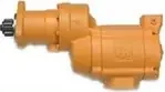
Ingersoll Rand 150T( ) G Series Inertia-Drive Turbine Air Starter Installation and Maintenance Manual (P7532)
Form P7532 is the Ingersoll Rand installation and maintenance manual for the Series 150T( ) G turbine-powered air starter with inertia drive, used to crank diesel and natural gas engines. It is written for installers and service technicians. It covers the model code, pinion data, flange orientation, mounting dimensions, vehicular and stationary piping, an illustrated parts list, lubrication quantities, disassembly, cleaning and inspection, assembly with torque values, and bench tests including a leak check for gas service.
Document at a Glance
- Publisher
- Ingersoll Rand
- Document type
- Installation & maintenance manual
- Form / number
- Form P7532, No. 04578126, Edition 2, August 2010
- Language
- English
- Pages
- 16
- File
- PDF, 1.9 MB
What's in This Document
| Section | Pages | What it covers |
|---|---|---|
| Product Safety Information and Operating Guideline | 2 | Intended use, reference to safety manual form 45558624 and the cranking time and cool-down rule. |
| Lubrication and Specifications (Pinion Data) | 2 | Gear oil and grease used and the pinion codes with teeth, pitch, diameters and rotation. |
| Model Coding and Flange Orientation | 3 | Breaks down each position of the 150T model code and shows the 18 flange orientation positions and bolt circle. |
| Placing the Starter in Service: Installation and Orientation | 4 | Hose and supply line sizing, sealing, gas venting, optional strainers and how to re-orient the housings. |
| Mounting the Starter | 4-5 | Receiver tank, relay valve, control valve or solenoid, gauge, hose routing and mounting bolt torque. |
| Mounting Dimensions | 6 | Dimension drawing with inlet and outlet threads, pinion travel, optional exhaust deflector and flange kit. |
| Typical Vehicular and Stationary Installations | 7-8 | Piping diagrams with Ingersoll Rand part numbers and notes for natural gas operation. |
| Cross-section, Exploded Views and Part List | 9-11 | Drawings and the item list of motor, gearing, drive and housing parts. |
| Maintenance: Lubrication and Disassembly | 12-13 | Oil and grease quantities, inertia drive cautions and the teardown sequence. |
| Cleaning, Inspection and Assembly | 13-14 | Cleaning rules, bearing and seal inspection, and reassembly of the drive gear, gear case, drive housing, intermediate gear case and motor housing. |
| Test and Inspection Procedure | 14 | Clutch ratcheting, freeness, motor action, pinion chamfer orientation and an immersion leak test. |
Key Specifications and Data
| Item | Value | Page |
|---|---|---|
| Application | Cranking diesel and natural gas fueled internal combustion engines | 2 |
| Drive type | Inertia drive (G in model code) | 3 |
| Cranking limit | If no start within 30 seconds, stop and let the starter cool 2-1/2 minutes | 2 |
| Inlet / exhaust outlet | 1 1/4-11 1/2 NPT inlet; 2-11 1/2 NPT outlet | 6 |
| Pinion travel | 1.000 in (25.40 mm) | 6 |
| Mounting bolt circle | 3 holes of 0.660 in on a 5.500 in (139.70 mm) bolt circle; 18 flange positions at 20 degrees | 3 |
| Supply line size | 1-1/4 in hose or pipe up to 15 ft; 1-1/2 in beyond 15 ft | 4 |
| Inlet strainer (optional) | 300 mesh, 50 micron filtration | 4 |
| Intermediate gear case oil | 55 ml (1.9 fl oz) 80W90 gear oil | 12 |
| Rear motor bearing oil | 7 ml (0.24 fl oz) 80W90 hypoid gear oil | 12 |
| Offset gear case grease | Approx. 0.24 kg (8 oz) Ingersoll Rand No. 11 grease | 12 |
| Mounting bolt torque | 100 ft-lb (136 Nm) or engine maker's specification | 5 |
| Drive housing cap screw torque | 100 in-lb (13 Nm) | 13 |
| Motor housing / inlet cover cap screw torque | 25 ft-lb (34 Nm) | 14 |
| Filler plug torque | 5-10 ft-lb (6.8-13.6 Nm) | 14 |
| Leak test | 40 psig (2.8 bar / 280 kPa) with exhaust plugged, immersed 30 seconds | 14 |
| Orientation positions | Drive housing 18 positions; exhaust port 4; air inlet 4 | 4 |
150T( ) G pinion data
| Pinion code | Teeth | Blank | DP/MOD | PD (in) | PD (mm) | PA | Rotation | OD (in) | OD (mm) |
|---|---|---|---|---|---|---|---|---|---|
| 5 | 12 | 12 | 8/10 | 1.625 | 41.28 | 20° | R | 1.75 | 44.45 |
| 6 | 11 | 12 | 6/8 | 2 | 50.8 | 20° | R | 2 | 50.8 |
| 11 | 11 | 12 | 6/8 | 2 | 50.8 | 20° | L | 2 | 50.8 |
150T model code positions (example 150T M G E 21 RH 6- 0 2 O)
| Position | Meaning |
|---|---|
| 150T | Starter |
| M | Motor |
| G | Inertia drive |
| E | Gear ratio |
| 21 | Drive housing |
| RH | Rotation |
| 6 | Pinion code |
| 0 2 O | Orientation: inlet, exhaust, drive housing |
Service Kits and Part Numbers
| Part number | Description | Page |
|---|---|---|
| ST544R-A53 | Motor assembly RH | 11 |
| ST544L-A53 | Motor assembly LH | 11 |
| ST599R-A53 | Motor assembly RH | 11 |
| ST599L-A53 | Motor assembly LH | 11 |
| ST500-A108B | Gear frame assembly | 11 |
| ST500-A37 | Gear case assembly (intermediate) | 11 |
| ST500-40 | Motor housing | 11 |
| ST500-202 | Inlet cover | 11 |
| ST500-674 | Muffler | 11 |
| ST500-A735 | Exhaust deflector assembly (optional) | 6 |
| ST500-K166 | Flange kit, 1.25 pipe (optional inlet flange kit) | 6 |
| 10BM-X37 | Gear case (offset) | 11 |
| 10BM-478 | Gear case cover | 11 |
| 150BME-17 | Pinion (offset gear) | 11 |
| 150BME-9 | Drive gear | 11 |
| ML50K-318 | Needle roller bearing | 11 |
| 150T-29 | Magnetic drain plug, 1/8 NPT | 11 |
| 150T-302 | Warning label | 11 |
| SRV125 | Starter relay valve, 1-1/4 in | 4 |
| SMB-618 | Starter control valve (brass, air) | 7 |
| SMBG-618 | Starter control valve (chrome, gas) | 7 |
| 150BMP-1051B | Solenoid valve, 12 VDC | 5 |
| 150BMP-1064L | Air pressure gauge | 7 |
| 150BMP-1056 | Check valve | 7 |
| TA-STR-100 | Starter instruction label | 5 |
| ST900-267-24 | 300 mesh strainer for 1-1/2 in lines | 4 |
| ST900-267-32 | 300 mesh strainer for 2 in lines | 4 |
| ST900-267-32F | 300 mesh strainer for 2 in lines (flange) | 4 |
| ST900-267-48 | 300 mesh strainer for 3 in lines | 4 |
| ST900-267-64 | 300 mesh strainer for 4 in lines | 4 |
Confirm part numbers against the serial and model plate of your starter. For any part not listed in our catalog, send us the number.
Mounting the starter (Overview)
- Use a receiver tank rated at least to the starter's maximum pressure; bleed and drain an in-service tank first.
- Fit the SRV125 relay valve to the tank with a 1-1/4 in short nipple, using the inlet marked IN.
- Mount the SMB-618 control valve or a solenoid valve, the TA-STR-100 label and the gauge, and connect them to the relay valve with 1/4 in hose.
- Run 1-1/4 in hose from the relay valve outlet to the starter and grease the ring gear teeth if possible.
- Mount the starter on the flywheel housing at 100 ft-lb (136 Nm) or the engine maker's figure.
- Pipe the exhaust away if needed, pressurize and soap-test all connections.
An outline only. Follow the full procedure, torque values and safety warnings in the document (from page 4).
Test and inspection after assembly (Overview)
- Turn the drive pinion by hand in the starter direction; it should advance smoothly to the stop.
- Turn it the opposite way; it should still turn by hand.
- Run the motor slowly on air and confirm the pinion turns the right way.
- Check that the pinion tooth chamfers are on the following side.
- Plug the exhaust, apply 40 psig and immerse for 30 seconds; any bubbles mean the unit is unfit for gas until resealed and retested.
An outline only. Follow the full procedure, torque values and safety warnings in the document (from page 14).
Frequently Asked Questions
What does the G mean in a 150T G air starter model?
In the 150T model code the G position stands for an inertia drive.
How long can a 150T G starter crank before resting?
If the engine does not start within 30 seconds, stop and let the starter cool for 2-1/2 minutes before trying again.
What oil goes in a 150T G starter?
55 ml (1.9 fl oz) of 80W90 gear oil in the intermediate gear case and 7 ml (0.24 fl oz) of 80W90 hypoid gear oil in the rear motor bearing reservoir; do not overfill.
Should the inertia drive threads be greased?
No. On inertia drive models the threaded area of the drive shaft is not lubricated, because grease there can collect dirt and impair operation.
What engines is the 150T G starter used on?
The manual says the Series 150()G starters are designed to crank diesel and natural gas fueled internal combustion engines.
Need the parts or the starter in this document? Send the model number from your starter's plate and we will confirm the right Ingersoll Rand part or replacement.
Source: Ingersoll Rand, Form P7532, No. 04578126, Edition 2, August 2010. Summary and tables prepared by AirStartersDirect.com, an authorized Ingersoll Rand air starter distributor; the PDF is the authoritative version. Page numbers refer to the PDF file. Reviewed October 2026.
Turbine Air Starter Category Links

Updated turbine starter from Ingersoll Rand for engines from 16-95 liters.

Powerful 70 hp turbine motor offers best-in-class performance in the harshest conditions!

NEWEST MODEL! Unlocks unprecedented productivity for engines ranging from 15 up to 150 liters!

Industrial duty air starter for engines 5 to 60 liters (Diesel). Commonly used in marine, trucking, transit, and oil & gas applications.

Industrial duty air starter for engines 16 to 80 liters (Diesel). Commonly used in mining and marine applications.

For engine displacement of: Diesel 16 to 320 liters Industry applications for the ST700 and ST900 Series starters - oil and gas, marine, power-gen, and transportation.

Industrial duty air starter for engines 5 to 60 liters (Diesel). Commonly used in marine, trucking, transit, and oil & gas applications.
Vane Air Starter, Gas Turbine Starter, and Engine Barring Motor Category Links

NEW! One Size fits engines up to 10+ liters.

For Diesel engines 8 - 32 liters.

Sealed for Gas applications.

For Diesel engines 3 to 20 liters.

For Diesel engines 16 - 320 liters.

For service work on diesel engines.
Questions? Need Help Finding The Right air Starter? Use Our Fast Response Form Below
