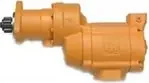
Ingersoll Rand literature · Installation & maintenance manual
Ingersoll Rand 150T( )GF Series Turbine Powered Air Starter Installation and Maintenance Manual (P7706, Edition 2)
Installation and maintenance information for the Ingersoll Rand 150T( )GF Series turbine powered air starters, the inertia-drive version of the 150T, used to crank diesel and natural gas engines. It guides installers through air system hook-up, housing orientation and mounting, and gives service technicians the parts list, optional equipment, lubrication quantities, overhaul sequence and a bench test that includes a leak check for gas operation.
Document at a Glance
- Publisher
- Ingersoll Rand
- Document type
- Installation & maintenance manual
- Form / number
- Form P7706, No. 04580205, Edition 2, May 2009
- Language
- English
- Pages
- 16
- File
- PDF, 1.3 MB
What's in This Document
| Section | Pages | What it covers |
|---|---|---|
| Product Safety Information | 2 | Intended use, lubricants, the cranking time guideline, model coding and pinion data. |
| Dimension drawing (Dwg. TP1928) | 3 | End view showing flange bolt circle, flange hole orientation and the eighteen drive housing positions. |
| Installation and Orientation of the Starter | 4 | General hook-up guidance, strainers, reorienting the housings and the first mounting steps. |
| Mounting the Starter (continued) | 5 | Control valve, gauge and hose connections, bolting the starter to the flywheel housing and leak testing the system. |
| Mounting Dimensions | 6 | Dimensioned side view with inlet and outlet thread sizes, optional flange kit and exhaust deflector. |
| Installation piping diagram | 7 | Typical air system layout with relay valve, control or solenoid valve, check valve, gauge and receiver tank. |
| Exploded, Cross-Section and End Views | 8-9 | Numbered drawings keyed to the parts list. |
| Part List and Optional Equipment | 10-11 | Part numbers for the starter components, motor assemblies, starter drives, kits and system valves. |
| Maintenance Section | 12-13 | Lubrication quantities, inertia drive cautions, disassembly, cleaning and inspection of parts. |
| Assembly | 13-14 | Reassembly of drive gear, gear cases, drive housing and motor housing with torque values. |
| Test and Inspection Procedure | 14 | Bench checks for clutch action, freeness, motor rotation, pinion chamfer and a submerged leak test. |
Key Specifications and Data
| Item | Value | Page |
|---|---|---|
| Intended use | Cranking diesel and natural gas fueled internal combustion engines | 2 |
| Drive type | Inertia drive (G in the model code) | 2 |
| Maximum cranking attempt | 30 seconds, then 2-1/2 minutes cool-down | 2 |
| Lubricants | 80W90 hypoid gear oil and Ingersoll Rand No. 130 grease | 2 |
| Intermediate gear case oil fill | 55 ml (1.9 fl.oz.) of 80W90 gear oil | 12 |
| Rear motor bearing oil fill | 7 ml (0.24 fl. oz.) of 80W90 hypoid gear oil | 12 |
| Offset gear case grease | About 0.24 kg (8 fl.oz) of No. 130 grease (Ingersoll Rand) | 12 |
| Mounting bolt torque | 100 ft-lb (136 Nm) | 5 |
| Drive housing cap screw torque | 100 in-lb (given as 11 Nm on page 4 and 13 Nm on page 13) | 4 |
| Motor housing cover cap screw torque | 25 ft-lb (34 Nm), tightened in 10 ft-lb (14 Nm) increments | 4 |
| Oil filler plug torque | 5 to 10 ft-lb (6.8 to 13.6 Nm) | 14 |
| Supply line size | 1-1/4 in. up to 15 ft (4.6 m); 1-1/2 in. over 15 ft (4.6 m) | 4 |
| Air inlet | 1-1/4 - 11-1/2 NPT (optional flange kit ST500-K166) | 6 |
| Exhaust outlet | 2 - 11-1/2 NPT | 6 |
| Mounting flange bolt circle | 5.500 in. (139.70 mm) | 3 |
| Housing orientation | Drive housing 18 positions; exhaust port 4 positions; air inlet 4 positions | 4 |
| Recommended inlet strainer | 300 mesh, 50-micron filtration | 4 |
| Leak test pressure | 40 psig (2.8 bar / 280 kPa), unit immersed 30 seconds | 14 |
Pinion data
| Pinion code | Number of teeth | Blank | DP/MOD | PD (in) | PD (mm) | PA |
|---|---|---|---|---|---|---|
| 5 | 12 | 12 | 8/10 | 1.625 | 41.28 | 20° |
| 6 | 11 | 12 | 6/8 | 2 | 50.8 | 20° |
| 11 | 11 | 12 | 6/8 | 2 | 50.8 | 20° |
Models Covered
Model codes as printed in the document. Linked codes go to the matching Ingersoll Rand starter in our catalog.
150TMG 150TLG 150TJG
Service Kits and Part Numbers
| Part number | Description | Page |
|---|---|---|
| 150TMG-SK1 | Seal kit | 11 |
| 150TMG-TK1 | Tune-up kit | 11 |
| 150TMFR-A53 | Motor assembly, 150TMG, RH | 10 |
| 150TMFL-A53 | Motor assembly, 150TMG, LH | 10 |
| 150TLFR-A53 | Motor assembly, 150TLG, RH | 10 |
| 150TLFL-A53 | Motor assembly, 150TLG, LH | 10 |
| 150TJFR-A53 | Motor assembly, 150TJG, RH | 10 |
| 150TJFL-A53 | Motor assembly, 150TJG, LH | 10 |
| 10BM-299-22 | Starter drive (one of three variants listed: RH 12 tooth, RH 11 tooth, LH 11 tooth) | 10 |
| 10BM-299-21 | Starter drive (one of three variants listed: RH 12 tooth, RH 11 tooth, LH 11 tooth) | 10 |
| 10BM-299-19 | Starter drive (one of three variants listed: RH 12 tooth, RH 11 tooth, LH 11 tooth) | 10 |
| ST500-K166 | Flange kit, 1-1/4 in. pipe | 11 |
| 150T-312 | Muffler | 11 |
| ST500-A735 | Exhaust deflector assembly | 11 |
| ST500-K740 | Exhaust tube kit | 11 |
| SMB-441 | Pipe sealant | 11 |
| 150BMP-1051B | Solenoid valve, 12 V | 11 |
| 150BMP-2451B | Solenoid valve, 24 V | 11 |
| SMB-618 | Starter control valve (brass, air) | 11 |
| SMBG-618 | Starter control valve (chrome, gas) | 7 |
| SRV-125 | Relay valve | 11 |
| 150BMP-1056 | Check valve | 11 |
| 150BMP-1054 | Check relief valve | 11 |
| 150BMP-1064 | Air pressure gauge | 5 |
| TA-STR-100 | Starter instruction label | 4 |
| ST900-267-24 | Inlet strainer for 1-1/2 in. lines | 4 |
| ST900-267-32 | Inlet strainer for 2 in. lines | 4 |
| ST900-267-32F | Inlet strainer for 2 in. lines (flange) | 4 |
| ST900-267-48 | Inlet strainer for 3 in. lines | 4 |
| ST900-267-64 | Inlet strainer for 4 in. lines | 4 |
Confirm part numbers against the serial and model plate of your starter. For any part not listed in our catalog, send us the number.
Assembling the drive housing (inertia drive) (Overview)
- If the drive housing bearing was removed, press a new one in unstamped end first until flush with the inside face of the housing boss, and work No. 130 grease into it.
- Do not clean the starter drive with solvent; if it looks dry, put No. 130 grease on the threads under the pinion.
- Wipe a thin film of No. 130 grease on the drive shaft and slide the starter drive onto it.
- Set the drive housing over the drive onto the gear case cover, turning it to the punch-marked orientation with the cap screw holes aligned.
- Fit the cap screws and lock washers and tighten to 100 in-lb.
An outline only. Follow the full procedure, torque values and safety warnings in the document (from page 13).
Bench test after reassembly (Overview)
- Turn the drive pinion by hand in the rotation direction; it should advance smoothly to the stop.
- Turn it the opposite way; the pinion should turn by hand.
- Run the motor slowly on an air hose and confirm the pinion turns the correct way; wrong rotation means incorrect motor assembly.
- Check that the chamfers on the pinion teeth are on the following side.
- Plug the exhaust, apply 40 psig (2.8 bar) to the inlet and immerse for 30 seconds in light oil or nonflammable solvent; any bubbles mean the unit is not fit for gas operation until sealed and retested.
An outline only. Follow the full procedure, torque values and safety warnings in the document (from page 14).
Frequently Asked Questions
Is the Ingersoll Rand 150T GF an inertia-drive starter?
Yes. The model coding labels the G position as inertia, and the maintenance section carries notes specific to the inertia drive, such as never washing it in solvent.
What is the seal kit number for the 150TMG starter?
The optional equipment list gives seal kit 150TMG-SK1 and tune-up kit 150TMG-TK1, covering the parts marked with one and two asterisks.
How is a rebuilt 150T GF starter checked before gas service?
With the exhaust plugged and 40 psig (2.8 bar) on the inlet, the unit is submerged for 30 seconds; if bubbles appear it is unfit for gas operation until the leak is fixed and retested.
What oil and grease does the 150T GF starter use?
80W90 gear oil fills the intermediate gear case (55 ml) and rear motor bearing reservoir (7 ml), and about 0.24 kg of Ingersoll Rand No. 130 grease lubricates the offset gear case.
What are the inlet and outlet thread sizes?
The mounting dimensions drawing shows a 1-1/4 - 11-1/2 NPT inlet and a 2 - 11-1/2 NPT outlet, with an optional ST500-K166 inlet flange kit.
Need the parts or the starter in this document? Send the model number from your starter's plate and we will confirm the right Ingersoll Rand part or replacement.
Source: Ingersoll Rand, Form P7706, No. 04580205, Edition 2, May 2009. Summary and tables prepared by AirStartersDirect.com, an authorized Ingersoll Rand air starter distributor; the PDF is the authoritative version. Page numbers refer to the PDF file. Reviewed October 2026.
Turbine Air Starter Category Links

Updated turbine starter from Ingersoll Rand for engines from 16-95 liters.
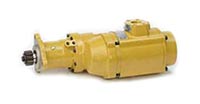
Powerful 70 hp turbine motor offers best-in-class performance in the harshest conditions!
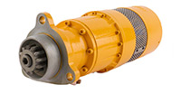
NEWEST MODEL! Unlocks unprecedented productivity for engines ranging from 15 up to 150 liters!
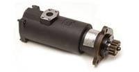
Industrial duty air starter for engines 5 to 60 liters (Diesel). Commonly used in marine, trucking, transit, and oil & gas applications.
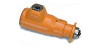
Industrial duty air starter for engines 16 to 80 liters (Diesel). Commonly used in mining and marine applications.

For engine displacement of: Diesel 16 to 320 liters Industry applications for the ST700 and ST900 Series starters - oil and gas, marine, power-gen, and transportation.

Industrial duty air starter for engines 5 to 60 liters (Diesel). Commonly used in marine, trucking, transit, and oil & gas applications.
Vane Air Starter, Gas Turbine Starter, and Engine Barring Motor Category Links

NEW! One Size fits engines up to 10+ liters.

For Diesel engines 8 - 32 liters.

Sealed for Gas applications.

For Diesel engines 3 to 20 liters.

For Diesel engines 16 - 320 liters.

For service work on diesel engines.
Questions? Need Help Finding The Right air Starter? Use Our Fast Response Form Below