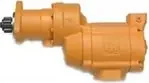
Ingersoll Rand literature · Operation & maintenance manual
Ingersoll Rand ST400G Series Gas Turbine Starter Operation and Maintenance Manual (04561858)
This manual covers operation, installation and maintenance of the Ingersoll Rand ST400G Series turbine starter, a flange-mounted inertia-drive starter that can run on air or on gas. It explains the model code and pinion choices, supply line sizing, strainers, relay and control valves, receiver tank requirements, a leak test for gas operation and typical vehicular and stationary piping layouts. The parts drawing, parts list, overhaul procedures with torques and lubricants, and a troubleshooting table support mechanics rebuilding the starter.
Document at a Glance
- Publisher
- Ingersoll Rand
- Document type
- Operation & maintenance manual
- Form / number
- No. 04561858, Edition 2, December 2007
- Language
- English and Chinese
- Pages
- 20
- File
- PDF, 1.6 MB
- Covers
- gas turbine, parts and accessories
What's in This Document
| Section | Pages | What it covers |
|---|---|---|
| General Product Safety Information | 2 | Warning topics including nameplate pressure, gas operation hazards, testing rebuilt starters and protective equipment, plus signal word definitions. |
| How to Order a Starter / Pinion Data | 3 | Model code breakdown (arc, air or gas, ratio, inertia drive, flange, rotation, pinion) and the three standard pinions. |
| Installation - General Information | 3 | Flange mounting, tools needed, supply line sizes, 300 mesh strainers, sealing threads and draining receiver moisture. |
| Orientation of the Starter | 3 | Re-clocking the drive housing to one of eighteen positions and the infinitely adjustable exhaust port. |
| Mounting the Air Starter / Gas-Operated Starters | 3-4 | Receiver tank requirements, relay valve, control valve, gauge and hose installation, mounting torque and the submerged leak test for gas units. |
| Piping Diagram | 5 | Typical vehicular and stationary inertia installations with Ingersoll Rand part numbers (Dwg. TPE_1026). |
| Dimensional Drawing | 6 | Outline dimensions, inlet and exhaust kits, weight and mounting notes (Dwg. TPE_1023). |
| ST400G Gas Turbine Starter Parts Drawing / Exploded Diagram / Parts List | 13-15 | Item-numbered drawings and part numbers, with motor assembly, drive shaft and drive listed per model (Dwg. TPE_1024). |
| Maintenance - Disassembly | 16 | Draining and checking magnetic plugs, removing the motor, drive housing, drive gearing and planet gears, then cleaning and inspection. |
| Maintenance - Assembly | 16-17 | Rebuilding the motor housing, drive gearing and drive housing with lubricant, fluid fill and torque values. |
| Troubleshooting Guide | 17 | Causes and fixes for a motor that will not run or has lost power. |
Key Specifications and Data
| Item | Value | Page |
|---|---|---|
| Power medium | Air or gas ('-' air, 'G' gas in model code) | 3 |
| Arc versions | STD 00, HALF 55, FULL 99 | 3 |
| Flange options | 01 SAE 01, 03 SAE 03 | 3 |
| Weight | 32 lbs | 6 |
| Supply line size | 1-1/4 in hose or pipe up to 15 ft; 2 in if longer than 15 ft | 3 |
| Inlet strainer | 300 mesh (50 micron); ST900-267-24 for 1-1/4 in, ST900-267-32 for 2 in, ST900-267-64 for 4 in lines | 3 |
| Drive housing positions | 18 radial positions at 20° | 6 |
| Starter mounting bolt torque | 100 ft-lb (136 Nm) | 4 |
| Gas leak test pressure | 40 psig (2.8 bar / 280 kPa), unit immersed 30 seconds | 4 |
| Receiver tank standard | SAE J10B or ASME, rated at or above the starter's maximum operating pressure | 3 |
| Relief valve setting (stationary) | 15 psi above regulator setting | 5 |
| Gearing fluid fill | 10 to 15 ml of automatic transmission fluid through the exhaust cover plug hole | 17 |
| Magnetic plug and pipe plug torque | 60 in-lb (7 Nm) | 16 |
| End cover and drive housing cap screw torque | 120 in-lb (13 Nm) | 17 |
| Lubricants | Ingersoll Rand No. 50 Oil on parts; Ingersoll Rand No. 130 Grease for open bearings and drive | 16 |
| Exhaust outlet | 2 in NPT; piped away for natural gas operation | 6 |
ST400G pinion data (page 3)
| Teeth | Blank | D.P. | P.A. | Rotation | Pinion no. |
|---|---|---|---|---|---|
| 11 | 12 | 6/8 | 20° | Right | 25 |
| 12 | 13 | 8/10 | 20° | Right | 29 |
| 11 | 13 | 6/8 | 20° | Left | 26 |
Model-specific parts: motor assembly, drive shaft and drive
| Model | Motor assembly (5) | Drive shaft (19) | Drive (24) |
|---|---|---|---|
| ST400GCI03R25 | ST400R-A53 | 04612792 | 10BM-299-21 |
| ST400GCI03L26 | ST400L-A53 | 04612792 | 10BM-299-19 |
| ST400GCI03R29 | ST400R-A53 | 04662882 | 10BM-299-22 |
| ST499GCI03R25 | ST499R-A53 | 04612792 | 10BM-299-21 |
| ST499GCI03L26 | ST499L-A53 | 04612792 | 10BM-299-19 |
| ST499GCI03R29 | ST499R-A53 | 04662882 | 10BM-299-22 |
Models Covered
Model codes as printed in the document. Linked codes go to the matching Ingersoll Rand starter in our catalog.
ST400GCI03R25 ST400GCI03L26 ST400GCI03R29 ST499GCI03R25 ST499GCI03L26 ST499GCI03R29
Service Kits and Part Numbers
| Part number | Description | Page |
|---|---|---|
| ST400R-A53 | Motor Assembly for ST400GCI03R25 and ST400GCI03R29 | 15 |
| ST400L-A53 | Motor Assembly for ST400GCI03L26 | 15 |
| ST499R-A53 | Motor Assembly for ST499GCI03R25 and ST499GCI03R29 | 15 |
| ST499L-A53 | Motor Assembly for ST499GCI03L26 | 15 |
| 04612792 | Drive Shaft (25 and 26 pinion models) | 15 |
| 04662882 | Drive Shaft (29 pinion models) | 15 |
| 10BM-299-21 | Drive, R25 models | 15 |
| 10BM-299-19 | Drive, L26 models | 15 |
| 10BM-299-22 | Drive, R29 models | 15 |
| ST400G-K17 | Inlet Flange Kit, includes mounting hardware | 15 |
| ST400G-K350 | Exhaust Elbow Kit, includes mounting hardware | 15 |
| 04613089 | Housing (item 4) | 15 |
| 04613410 | Cover End (item 1) | 15 |
| 9BM-300-H2 | Drive Housing (item 20) | 15 |
| ST400-37A | Ring Gear (item 13) | 15 |
| ST400-10A | Planet Gear, qty 3 (item 7) | 15 |
| ST400-278 | Planet gear Bearing, qty 3 (item 8) | 15 |
| ST400-22 | Bearing, qty 2 (item 14) | 15 |
| ML50K-318 | Drive housing Bearing (item 23) | 15 |
| 04561114 | Seal (item 17) | 15 |
| ST400-244 | O-Ring, qty 5 (item 3) | 15 |
| 04658621 | Magnetic Plug, qty 3 (item 10) | 15 |
| ST400-111 | Front Deflector (item 6) | 15 |
| SRV125 | Starter Relay Valve, 1-1/4 in | 4 |
| SMB-G618 | Starter Control Valve (dash or panel mount) | 4 |
| 150BMP-1064 | Air Pressure Gauge | 4 |
| 150BMP-1051B | Solenoid Valve, 12 volt (optional air-only control circuit) | 5 |
| ST900-267-24 | 300 mesh strainer for 1-1/4 in lines | 3 |
| ST900-266-24 | Replacement strainer element, 1-1/4 in | 3 |
| SMB-441 | Thread sealant | 3 |
Confirm part numbers against the serial and model plate of your starter. For any part not listed in our catalog, send us the number.
Leak testing a gas-operated ST400G starter (Overview)
- Coat the housing cover end plug and lubricator port plug with a thin film of sealant as they go in.
- Plug the exhaust and connect an air line to the inlet.
- Regulate the air to 40 psig (2.8 bar) and submerge the starter for 30 seconds in light oil or non-flammable solvent.
- Any bubbles mean the unit is not fit for gas service; tighten or seal the leaking joint and test again.
An outline only. Follow the full procedure, torque values and safety warnings in the document (from page 4).
Reassembling the ST400G drive housing (Overview)
- If removed, press a new drive housing bearing in, unstamped end first, until flush with the boss and work No. 130 grease into it.
- Coat the drive shaft surface with a thin film of No. 130 grease.
- Fit the thrust washer, bevelled inner ring down, then the starter drive on the drive shaft.
- Set the drive housing over the drive onto the motor housing, rotating it to the required orientation with the screw holes aligned.
- Install the drive housing cap screws and washers and tighten to 120 in-lb (13 Nm).
An outline only. Follow the full procedure, torque values and safety warnings in the document (from page 17).
Frequently Asked Questions
Can the ST400G starter run on natural gas?
Yes. The manual says the ST400G is designed for gas operation, notes it is not fully sealed in dynamic operation, and calls for the exhaust and relief valve outlet to be piped away to a safe location.
What size supply line does an ST400G starter need?
Use 1-1/4 in hose or pipe for supply lines up to 15 feet long and 2 in hose or pipe for longer runs, with as few tees and elbows as possible.
What torque is used to mount the ST400G starter to the engine?
The mounting bolts are tightened to 100 ft-lb (136 Nm).
What fluid goes in the ST400G gearing?
After fitting the exhaust cover, 10 to 15 ml of automatic transmission fluid is added through the pipe plug hole, and the plug is torqued to 60 in-lb (7 Nm).
How much does the ST400G starter weigh?
The dimensional drawing gives a starter weight of 32 lbs.
Need the parts or the starter in this document? Send the model number from your starter's plate and we will confirm the right Ingersoll Rand part or replacement.
Source: Ingersoll Rand, No. 04561858, Edition 2, December 2007. Summary and tables prepared by AirStartersDirect.com, an authorized Ingersoll Rand air starter distributor; the PDF is the authoritative version. Page numbers refer to the PDF file. Reviewed October 2026.
Turbine Air Starter Category Links

Updated turbine starter from Ingersoll Rand for engines from 16-95 liters.

Powerful 70 hp turbine motor offers best-in-class performance in the harshest conditions!

NEWEST MODEL! Unlocks unprecedented productivity for engines ranging from 15 up to 150 liters!

Industrial duty air starter for engines 5 to 60 liters (Diesel). Commonly used in marine, trucking, transit, and oil & gas applications.

Industrial duty air starter for engines 16 to 80 liters (Diesel). Commonly used in mining and marine applications.

For engine displacement of: Diesel 16 to 320 liters Industry applications for the ST700 and ST900 Series starters - oil and gas, marine, power-gen, and transportation.

Industrial duty air starter for engines 5 to 60 liters (Diesel). Commonly used in marine, trucking, transit, and oil & gas applications.
Vane Air Starter, Gas Turbine Starter, and Engine Barring Motor Category Links

NEW! One Size fits engines up to 10+ liters.

For Diesel engines 8 - 32 liters.

Sealed for Gas applications.

For Diesel engines 3 to 20 liters.

For Diesel engines 16 - 320 liters.

For service work on diesel engines.
Questions? Need Help Finding The Right air Starter? Use Our Fast Response Form Below
