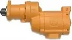
Ingersoll Rand literature · Installation & maintenance manual
Ingersoll Rand TS900 Series Turbine-Powered Starter Installation and Maintenance Manual (P7336)
This is the Ingersoll Rand installation and maintenance manual for the Series TS900 turbine-powered starters, built for air or gas operation in off-highway, marine and stationary engine applications. It is intended for installers and service technicians. It covers operating guidelines, installation and orientation, barring the engine, ordering codes, a parts listing with tune-up and rebuild kits, lubrication, disassembly and assembly of the exhaust cover, motor, clutch, gear case and drive housing, test procedures, troubleshooting and a maintenance schedule based on number of starts.
Document at a Glance
- Publisher
- Ingersoll Rand
- Document type
- Installation & maintenance manual
- Form / number
- Form P7336, No. 04575544, Edition 1
- Language
- English
- Pages
- 27
- File
- PDF, 1.0 MB
- Covers
- gas turbine
What's in This Document
| Section | Pages | What it covers |
|---|---|---|
| Warning Label Identification and Operating Guidelines | 1-2 | Safety warnings, gas operation cautions, pressure limits, oiling the exhaust cover and the strainer requirement for gas service. |
| Placing the Starter in Service: Installation | 4 | Piping, strainers, sealant, gas venting, pressure regulation, supply line layout and mounting torque. |
| Barring Over the Engine and Orientation of the Starter | 4 | Using the rotor shaft hex socket to turn the engine and rotating the drive housing or exhaust cover in the field. |
| Mounting Dimensions and Piping/Installation Drawings | 5-8 | Drawing pages for dimensions and piping layouts (images only, no extractable text). |
| How to Order a Starter | 9 | Part number code structure and maximum supply pressure and pinion data for two listed models. |
| Detailed Illustrations and Parts Listing | 10-14 | Exploded drawings, the TS900 parts list with tune-up and rebuild kits, and the motor assembly drawing. |
| Lubrication and Disassembly | 15-16 | Oil and grease points, then removal of the exhaust cover, motor assembly, drive housing, clutch and planet gear frame. |
| Assembly | 16-18 | Rebuilding the exhaust cover, clutch, gear case and drive housing with torque values and oil fill. |
| Test and Inspection Procedure | 18 | Hand rotation checks, an air run test and an immersion leak test after reassembly. |
| Troubleshooting Guide | 19 | Symptoms, probable causes and fixes for no-run, low power, oil blowing out and leakage. |
| TS900 Maintenance Schedule | 20 | Service actions every 500 starts and the parts to replace at 1500 and 3000 starts. |
| Additional Parts Listing Pages | 24-27 | Parts list pages that include motor assemblies for 725, 750 and 799 models in A and B ratios and B to E flanges. |
Key Specifications and Data
| Item | Value | Page |
|---|---|---|
| Maximum supply pressure (TS999GZFA-L, TS999GZCD-LE) | 90 psi (620 kPa) | 9 |
| Operating medium | Air or gas; off-highway, marine and stationary applications | 9 |
| Motor housing oil | 300 ml of C32 grade turbine oil through the side plug hole | 15 |
| Exhaust cover oil | 15 ml of turbine oil at the plug marked oil here | 2 |
| Oil change interval | Annually or every 500 starts | 17 |
| Clutch replacement interval | After 1500 starts | 17 |
| Inlet strainer | 300 mesh, 50 micron filtration; required in gas applications | 4 |
| Mounting cap screw torque | 40-45 ft-lb (54-61 Nm) | 4 |
| Drive housing cap screw torque | 28 ft-lb (38 Nm) | 4 |
| Starter assembly cap screw torque (re-orienting exhaust cover) | 60 ft-lb (81.4 Nm) in 20 ft-lb (27 Nm) increments | 4 |
| Clutch screw torque | 90 ft-lb (122 Nm) with Loctite 242 | 18 |
| Pressure relief valve setting | 15 psi above the regulator setting | 4 |
| Bench run test | 90 psi (6.2 bar / 620 kPa) through a 3/8 in (9 mm) supply line | 18 |
| Leak test | 20 psi (1.38 bar / 138 kPa) for 30 seconds while immersed | 18 |
| Dynamic timing rest period | 2 minutes between 30 second measurements | 2 |
Listed models: maximum supply pressure and pinion data
| Model | Max supply pressure (psi/kPa) | No. of teeth | Diametral pitch | Pitch diameter | PA |
|---|---|---|---|---|---|
| TS999GZFA-L | 90/620 | 24 | 20/30 | 1.2 | 30 |
| TS999GZCD-LE | 90/620 | 16 | 20/30 | .8 | 30 |
Maintenance schedule by number of starts
| Starts | Component | Action |
|---|---|---|
| Every 500 | Turbine oil | Change |
| Every 500 | All external cap screws | Check torque |
| Every 500 | Strainer | Check element |
| 1500 and 3000 | Clutch TS700-359 | Change |
| 1500 and 3000 | Rear bearing SS875-399 | Change |
| 1500 and 3000 | Front bearing SS875-278 | Change |
| 1500 and 3000 | Seal TS700-54 | Change |
| 1500 and 3000 | O-ring Y327-158 | Change |
| 1500 and 3000 | O-ring Y327-123 | Change |
| 1500 and 3000 | Bearing TS700-22 | Change |
Inlet strainers and replacement elements
| Line size | Strainer | Replacement element |
|---|---|---|
| 1 in | ST900-267-24 | ST900-266-24 |
| 2 in | ST900-267-32 | ST900-266-32 |
| 4 in | ST900-267-64 | ST900-266-64 |
Models Covered
Model codes as printed in the document. Linked codes go to the matching Ingersoll Rand starter in our catalog.
Service Kits and Part Numbers
| Part number | Description | Page |
|---|---|---|
| TS700-TK1 | Tune-up kit | 13 |
| TS700-RM1 | Rebuild kit | 13 |
| ST799R-A53A | Motor assembly | 13 |
| TS700-359 | Clutch | 13 |
| SS875-399 | Rear bearing | 13 |
| SS875-278 | Front bearing | 13 |
| TS875-14 | Clutch housing | 13 |
| TS700-8S | Drive shaft | 13 |
| TS900-A108 | Planet gear frame | 13 |
| TS875-300 | Drive housing | 13 |
| TS700-54 | Drive housing shaft seal | 13 |
| TS710A-13F | Splined shaft, A model | 13 |
| 04612834 | Splined shaft, D model | 13 |
| 04559464 | C flange | 13 |
| 04559175 | E flange | 13 |
| 04334850 | Gear ring | 13 |
| ST900-A40 | Motor housing assembly | 13 |
| ST900-372 | Gear case | 13 |
| ST700-350 | Exhaust kit / directional housing exhaust cover | 13 |
| ST700K-350 | 90 degree exhaust housing for piping away the exhaust | 4 |
| ST700-K166 | Inlet flange kit (flange, mounting bolts and lock washers) | 13 |
| ST700-351 | Exhaust flange | 13 |
| Y327-158 | Front gear case O-ring | 13 |
| Y327-123 | Splined shaft O-ring | 13 |
| TS700-22 | Bearing | 13 |
| ST900-267-24 | 300 mesh strainer for 1 in lines | 4 |
| ST900-267-32 | 300 mesh strainer for 2 in lines | 4 |
| ST900-267-64 | 300 mesh strainer for 4 in lines | 4 |
| TS725R-A53A | Motor assembly, 725 RH rotation, A ratio (additional parts pages) | 26 |
| TS799R-A53A | Motor assembly, 799 RH rotation, A ratio (additional parts pages) | 26 |
Confirm part numbers against the serial and model plate of your starter. For any part not listed in our catalog, send us the number.
Re-orienting the drive housing or exhaust cover (Overview)
- To move the drive housing, remove the cap screws holding it to the gear case.
- Turn the drive housing to the new position without taking it off the gear case.
- Refit the cap screws and torque them to 28 ft-lb (38 Nm).
- To move the directional exhaust cover, remove the starter assembly cap screws and rotate the cover, keeping it on the motor housing.
- Reinstall the cap screws and tighten to 60 ft-lb (81.4 Nm) in 20 ft-lb (27 Nm) steps.
An outline only. Follow the full procedure, torque values and safety warnings in the document (from page 4).
Lubricating the starter after service (Overview)
- Coat every O-ring with O-ring lubricant.
- Wipe both end splines of the splined shaft with Ingersoll Rand No. 130 grease.
- With the exhaust elbow plug up, pour 15 ml of C32 grade turbine oil in and refit the plug.
- Lay the starter on its side with the side plug hole up and add 300 ml of C32 grade turbine oil to the motor housing.
- Seal all plugs with the pipe sealant named in the manual, and change the oil annually or every 500 starts.
An outline only. Follow the full procedure, torque values and safety warnings in the document (from page 17).
Frequently Asked Questions
What oil does a TS900 turbine starter use?
The manual calls for C32 grade turbine oil: 300 ml through the side plug hole in the motor housing and 15 ml at the plug in the exhaust cover.
How often should the TS900 be serviced?
Change the oil annually or every 500 starts, checking cap screw torque and the strainer element at the same interval. The clutch, front and rear bearings, seal and O-rings listed in the schedule are changed at 1500 starts.
Is a strainer required on a TS900 starter?
Yes. The manual requires a strainer in each starter's inlet line and specifically for gas use. Ingersoll Rand lists 300 mesh (50 micron) strainers ST900-267-24, ST900-267-32 and ST900-267-64 for 1, 2 and 4 inch lines.
Can the TS900 be used to bar over the engine?
The rotor shaft has a 1/4 in hex socket in its end that can turn the engine. It is reached by removing the 1/4 in NPT plug from the directional exhaust housing.
What is the maximum supply pressure for the TS900?
Both models listed in the ordering section, TS999GZFA-L and TS999GZCD-LE, are rated at 90 psi (620 kPa) maximum supply pressure. The nameplate rating must never be exceeded.
Need the parts or the starter in this document? Send the model number from your starter's plate and we will confirm the right Ingersoll Rand part or replacement.
Source: Ingersoll Rand, Form P7336, No. 04575544, Edition 1. Summary and tables prepared by AirStartersDirect.com, an authorized Ingersoll Rand air starter distributor; the PDF is the authoritative version. Page numbers refer to the PDF file. Reviewed October 2026.
Turbine Air Starter Category Links

Updated turbine starter from Ingersoll Rand for engines from 16-95 liters.

Powerful 70 hp turbine motor offers best-in-class performance in the harshest conditions!

NEWEST MODEL! Unlocks unprecedented productivity for engines ranging from 15 up to 150 liters!

Industrial duty air starter for engines 5 to 60 liters (Diesel). Commonly used in marine, trucking, transit, and oil & gas applications.

Industrial duty air starter for engines 16 to 80 liters (Diesel). Commonly used in mining and marine applications.

For engine displacement of: Diesel 16 to 320 liters Industry applications for the ST700 and ST900 Series starters - oil and gas, marine, power-gen, and transportation.

Industrial duty air starter for engines 5 to 60 liters (Diesel). Commonly used in marine, trucking, transit, and oil & gas applications.
Vane Air Starter, Gas Turbine Starter, and Engine Barring Motor Category Links

NEW! One Size fits engines up to 10+ liters.

For Diesel engines 8 - 32 liters.

Sealed for Gas applications.

For Diesel engines 3 to 20 liters.

For Diesel engines 16 - 320 liters.

For service work on diesel engines.
Questions? Need Help Finding The Right air Starter? Use Our Fast Response Form Below
