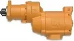
Ingersoll Rand literature · Installation & maintenance manual
Ingersoll Rand TS1401 Series Turbine Air Starter Installation and Maintenance Manual (P7166)
Form P7166 is the Ingersoll Rand installation and maintenance manual for the Series TS1401 turbine-powered starter, a two-motor air or gas starter that mounts to a turbine through a gear case and customer-supplied coupling. It is written for installers and overhaul technicians. It covers dimensions, piping, field assembly of the three supplied sub-assemblies, parts lists for the gear case, motor and complete starter, disassembly and assembly with a torque chart, oil fills, test procedures, troubleshooting and a start-based maintenance schedule.
Document at a Glance
- Publisher
- Ingersoll Rand
- Document type
- Installation & maintenance manual
- Form / number
- Form P7166, No. 03540697, Edition 4, April 2007
- Language
- English
- Pages
- 20
- File
- PDF, 1.3 MB
- Covers
- gas turbine
What's in This Document
| Section | Pages | What it covers |
|---|---|---|
| General Product Safety Information and Operating Guidelines | 2 | Safety warnings on pressure ratings, gas operation, testing rebuilt starters and protective equipment, plus the strainer requirement. |
| Placing the Starter in Service (Dimensions) | 3 | Dimension drawing showing the J518C flanges, slip-on exhaust flange, mounting holes and oil drain. |
| Installation and Mounting the Starter | 4-5 | Hose versus pipe, strainers, sealing, gas venting, maximum pressures by model, mounting the gear case and both motors, and control piping. |
| Assembly Instructions | 5 | How to fit the gear case and the two motor assemblies, which are supplied as separate sub-assemblies. |
| Gear Assembly and Motor Assembly Parts Lists | 6-7 | Parts for the intermediate gear case and planet gear frame, and the motor items sold only as an assembly. |
| Sectional View, Exploded View and Parts List | 8-10 | Drawings and the full item-numbered parts list including motors by model, kits and gear case parts. |
| Maintenance: Disassembly | 11-12 | Teardown of the exhaust elbow, motors, intermediate gear case, idler gear frame and output gear case. |
| Torque Chart | 12 | Assembly torque and sealant requirement for the main fasteners. |
| Assembly | 13-14 | Rebuild of idler gears, intermediate gear case, motors, exhaust cover and gear case with oil fill amounts. |
| Test and Inspection Procedure | 15 | Freeness, motor action, seal hold tests, rotation checks and shaft concentricity for D ratio units. |
| Trouble Shooting Guide and Maintenance Schedule | 15-16 | Symptom table with causes and fixes, and service actions by number of starts. |
Key Specifications and Data
| Item | Value | Page |
|---|---|---|
| Maximum supply pressure by model | TS1400 225 psi (1551 kPa); TS1435 195 psi (1343 kPa); TS1450 150 psi (1034 kPa); TS1475 120 psi (827 kPa); TS1499 90 psi (620 kPa) | 4 |
| Operating medium | Air or gas; discharges must be piped to a safe area with flammable gas | 4 |
| Motors | Two motor assemblies per starter | 5 |
| Supply line size | 2 in hose or pipe up to 15 ft; 2 1/2 in if longer | 4 |
| Inlet strainer | 150 mesh, 100 micron filtration; ST900-267-24 strainer (2) required | 4 |
| Mounting flanges | SAE J518C type flanges; slip-on exhaust flange for 3 1/2 in pipe | 3 |
| Motor bolt torque | 55 ft-lb (74.5 Nm), tightened alternately | 4 |
| Intermediate pinion retaining screw torque | 90 ft-lb (122 Nm) | 13 |
| Drive gear shaft torque | 150 ft-lb (203 Nm), left-hand thread | 14 |
| Idler gear frame cap screw torque | 8 ft-lb (10.8 Nm) with sealant | 13 |
| Shoulder screw torque | 45 ft-lb (61 Nm) | 12 |
| Plug torque | 5-10 ft-lb (6.8-13.6 Nm) | 15 |
| Motor housing oil fill | 175 ml (about 1/3 pint) C32 grade turbine oil through the side plug; do not overfill | 14 |
| Exhaust elbow oil fill | 15 ml C32 grade turbine oil | 14 |
| Service intervals | Oil every 500 starts; motor assembly every 1000 starts; all bearings and seals at 1500 starts | 14 |
| Bench test pressures | Run 90 psig (6.2 bar / 620 kPa) via 3/8 in line; seal tests 20 psig (1.38 bar), hold within 5 psi for 30 s | 15 |
| D ratio shaft tolerance | Pilot concentric within .008 TIR max; mounting face square within .004 TIR max | 15 |
TS1401 series maximum allowable supply pressure
| Model | Max supply pressure (psi/kPa) |
|---|---|
| TS1400 | 225/1551 |
| 190475-101 | 225/1551 |
| TS1435 | 195/1343 |
| 190475-300 | 195/1343 |
| TS1450 | 150/1034 |
| TS1475 | 120/827 |
| TS1499 | 90/620 |
TS1401 torque chart
| Part no. | Assembly torque |
|---|---|
| CE110-29 | 8 ft-lb (10.8 Nm) |
| ST700-2579 | 55 ft-lb (74.5 Nm) |
| SS1600-182 | 45 ft-lb (61 Nm) |
| WE205-817 | 90 ft-lb (122 Nm) |
| SS1600-8 | 150 ft-lb (203 Nm) |
| ST900-2574 | 55 ft-lb (74.5 Nm) |
Models Covered
Model codes as printed in the document. Linked codes go to the matching Ingersoll Rand starter in our catalog.
Service Kits and Part Numbers
| Part number | Description | Page |
|---|---|---|
| TS1401-TK1 | Tune up kit | 10 |
| TS1401-RM1 | Rebuild kit (arc-specific) | 10 |
| TS1401-RM2 | Rebuild kit (arc-specific) | 10 |
| TS1401-RM3 | Rebuild kit (arc-specific) | 10 |
| TS1401-RM4 | Rebuild kit (arc-specific) | 10 |
| SS1600-APF-C-1329 | Gear kit | 10 |
| ST725R-A53A | Motor assembly, RH (925 models) | 10 |
| ST725L-A53A | Motor assembly, LH (925 models) | 10 |
| ST735R-A53A | Motor assembly, RH (935 models) | 10 |
| ST735L-A53A | Motor assembly, LH (935 models) | 10 |
| ST750R-A53A | Motor assembly, RH (950 models) | 10 |
| ST750L-A53A | Motor assembly, LH (950 models) | 10 |
| ST799R-A53A | Motor assembly, RH (999 models) | 10 |
| ST799L-A53A | Motor assembly, LH (999 models) | 10 |
| ST999-A37 | Intermediate gear case assembly | 6 |
| ST900-A108 | Planet gear frame assembly | 6 |
| 04324596 | Carrier / ring gear | 6 |
| ST900-10 | Idler gear (3) | 6 |
| ST900-A40 | Motor housing assembly | 10 |
| ST700K-350 | Exhaust kit | 10 |
| ST700-K166 | Inlet flange kit (flange, O-ring, bolts, lock washers) | 10 |
| SS1600-37 | Gear case | 10 |
| ST700-776 | Transit retaining nut on the motor bolts (removed at installation) | 5 |
| ST900-267-24 | Strainer (1 in lines per text) | 4 |
| ST900-267-32 | Strainer for 2 in lines | 4 |
| ST900-267-64 | Strainer for 4 in lines | 4 |
| SRV150SS | Relay valve, 1 1/2 in | 4 |
| SMB-G618 | Starter control valve | 4 |
| SS825-1064 | Pressure gauge | 4 |
Confirm part numbers against the serial and model plate of your starter. For any part not listed in our catalog, send us the number.
Fitting the gear case and motors to the turbine (Overview)
- Remove protective paper and tape and check finished surfaces and O-rings for adhesive, nicks or burrs.
- Lubricate the gear case O-ring, fit the customer-supplied coupling on the drive clutch jaw and mount the gear case on the engine.
- Check that the gear and driven jaw lugs line up with the coupling, then tighten the mounting nuts.
- Remove the ST700-776 transit nut, lubricate the motor O-rings and insert one motor so its pinion meshes with the drive gear.
- Confirm inlet and exhaust orientation and tighten the motor bolts alternately to 55 ft-lb (74.5 Nm); repeat for the second motor.
An outline only. Follow the full procedure, torque values and safety warnings in the document (from page 5).
Test and inspection after overhaul (Overview)
- Turn the drive shaft pinion by hand to confirm the motor and gearing turn freely.
- Run the starter in a vise on 90 psig through a 3/8 in line; it should run smoothly.
- Plug the exhaust and apply 20 psig to the motor inlet; pressure must hold within 5 psi for 30 seconds with no gear case leaks.
- Check motor and drive rotation against the nameplate and confirm the specified orientation.
- On D ratio units, indicate the pilot diameter and mounting face for concentricity and squareness.
An outline only. Follow the full procedure, torque values and safety warnings in the document (from page 15).
Frequently Asked Questions
What is the maximum air pressure for a TS1400 series starter?
It depends on the model: TS1400 225 psi, TS1435 195 psi, TS1450 150 psi, TS1475 120 psi and TS1499 90 psi.
How many motors does the TS1401 starter have?
Two. The starter is supplied as a gear case plus two motor assemblies, and each motor is fitted to the gear case and bolted down separately.
How much oil goes in a TS1401 starter?
About 175 ml of C32 grade turbine oil through the motor housing side plug and 15 ml at the exhaust elbow plug; the oil is changed every 500 starts.
How often should the TS1401 motor assembly be replaced?
The manual says the motor should be replaced every 1000 starts, with all bearings and seals replaced at 1500 starts per the schedule.
Can the TS1401 run on gas?
Yes, it is designed for air or gas operation; with flammable gas all discharges must be piped to a safe area.
Need the parts or the starter in this document? Send the model number from your starter's plate and we will confirm the right Ingersoll Rand part or replacement.
Source: Ingersoll Rand, Form P7166, No. 03540697, Edition 4, April 2007. Summary and tables prepared by AirStartersDirect.com, an authorized Ingersoll Rand air starter distributor; the PDF is the authoritative version. Page numbers refer to the PDF file. Reviewed October 2026.
Turbine Air Starter Category Links

Updated turbine starter from Ingersoll Rand for engines from 16-95 liters.

Powerful 70 hp turbine motor offers best-in-class performance in the harshest conditions!

NEWEST MODEL! Unlocks unprecedented productivity for engines ranging from 15 up to 150 liters!

Industrial duty air starter for engines 5 to 60 liters (Diesel). Commonly used in marine, trucking, transit, and oil & gas applications.

Industrial duty air starter for engines 16 to 80 liters (Diesel). Commonly used in mining and marine applications.

For engine displacement of: Diesel 16 to 320 liters Industry applications for the ST700 and ST900 Series starters - oil and gas, marine, power-gen, and transportation.

Industrial duty air starter for engines 5 to 60 liters (Diesel). Commonly used in marine, trucking, transit, and oil & gas applications.
Vane Air Starter, Gas Turbine Starter, and Engine Barring Motor Category Links

NEW! One Size fits engines up to 10+ liters.

For Diesel engines 8 - 32 liters.

Sealed for Gas applications.

For Diesel engines 3 to 20 liters.

For Diesel engines 16 - 320 liters.

For service work on diesel engines.
Questions? Need Help Finding The Right air Starter? Use Our Fast Response Form Below
